Autocad Lt Changing a Metric Drawing to Standard Dimentions

Introduction to Units in Autocad
You can set the type and precision of units with the AutoCAD Drawing Units dialog box you will use in the drawing. There are two types of unit display options in the Drawing Units dialog box control: length and angle. And also, this tool helps to control the precision by these unit values that can be occupied for length and angle measurement. Here in this article, we are going to see how to change units in Autocad.
The following procedures will be affected by unit settings:
- The status bar coordination
- predict the drawing for a distance or area with the format of the values
- Entering coordinates, distances, and angles at the Command line with the format of the values
In AutoCAD, drawing units also used to measure the distance. According to the drawing, one drawing unit be the same as in one millimeter, one inch, one mile or one meter. before you set the drawing units' format, you must decide what drawing units to use.
The linear units including the following format settings
- Architectural: A measurement contains the length of 15.5 units, output as 1'-3 1/2"
- Decimal: A measurement contains the length of 15.5 units, output as 15.5000
- Engineering: A measurement contains a length of 15.5 units, output as 1'-3.5."
- Fractional: A measurement contains the length of 15.5 units, output as 15 1/2
- Scientific: A measurement contains the length of 15.5 units, output as 1.5500E+01
1. Architectural units
Dimensions are allowed in the format of feet, inches, and fractional parts of an inch, such as 6′-11.5″. Example: Twelve inches is automatically converted to 1 foot. Architectural units were supporting residential and commercial planning and construction drawings. AutoCAD can display the smallest fraction that is 2~/". In AUTOCAD As 6 inches are assumed to enter by 6. And also important note is Inches are considered as the default unit.
2. Decimal units
Dimensions are allowed in the format of units in AutoCAD, such as 1.75 or 3.625. Decimal units are generally supporting mechanical drafting because of ANSI YI4. Engineering drawings were normally used 5M Dimensioning, and Tolerancing standards specify that decimal inch or metric units in millimeters. AutoCAD can display a maximum of eight decimal places. But an important note is Decimal is considered as the default unit.
3. Engineering units
Dimensions are allowed in the format of feet, inches, and decimal parts of an inch, such as 6′-5.25″.It can automatically convert and displays 12 inches as 1 foot And also important note is Inches are considered as the default unit. In AUTOCAD, As 6 inches are assumed to enter by 6. This (') symbol is used to enter the feet. Units in AutoCAD represents the Each engineering unit as one inch. Examples of typical civil drafting projects were constructional drawings and topographic maps for planning and constructing highways and harbours.
4. Fractional units
Dimensions are allowed in the format of a group of units and segments of units as a fraction, for example, 26~. Fractional units can be in the form of feet, miles, or inches. Fractions can represent the system of measure. As with architectural units, AutoCAD can display the smallest fraction that is 2~t.
5. Scientific units
Dimensions are allowed in the format as a real number raised to a pour of 10, such as I25E+02. The system of measurement can be represented by scientific notation. You can use scientific notation primarily for working with very large numbers.
Angular Measurement
AutoCAD also has five different angular measurement options. Descriptions of the angular measurement options for AutoCAD are as follows:
- Decimal degrees: Displays angular measurement in the format of Real numbers with up to eight decimal places. In AutoCAD, This is the default type of angular measurement.
- Deg/Min/Sec: Displays angular measurement in the format of degrees, minutes, and seconds. ASCII characters also used for representation, for example, 30d 12'38". Decimal places were denoted the Measurements of less than I second.
- Grads: Displays angular measurement in the form of grads, appears as like 37g. 100 grads are equal to Ninety degrees.
- Radians: Displays angular measurement in the format of radians. I80/pi degrees are termed as radian.
- Surveyor's units: Displays angular measurement in the format of degrees, minutes, and seconds together with quadrant bearings. An example is N45dI2'25″E. basically Circle divided into four quadrants, so no angular value can be greater than 90 degrees.
Angle Display Precision
The drawing requirements tend to denote the degree of accuracy for angles. Mechanical drawings were consisting of minutes of Two-place degrees or decimal degrees. Degrees, minutes, and seconds help to create the Mapmaking with civil drawings.
The angle display precision can be easily changed in the form of the Units Control dialog box. As noted,
- Accessing the Drawing Units dialog box with a set of units. The Drawing Units dialog box can access in one of the following ways:
- Command prompted units or
- menu bar formats by selecting units.
- To change the precision, select the Precision text box, and then the Precision list box appears and uses the pointing device to select the precision you want.
For example,
- A mechanical engineer who calculates the measurement in millimeters will set the format of linear units to decimal.
- An architect who calculates the measurement in feet and inches, the format of linear units will be set to architectural. The display style of the drawing units on-screen controls by drawing unit formats, such as the dialog boxes and prompts, shows coordinates and values.
Angle Direction
AutoCAD predicting that 0 degrees are going onto the right, i.e. 3 O clock or east. Also, by default, angles increase in the form of counterclockwise direction, The angle direction and location of 0 degrees, by selecting Direction options in the Units Control dialog box.
To set the format of the drawing units.
1. Click ➤ Drawing utility ➤ Units.
 –
–
2. In the Drawing Units dialog box, under Length, select the following values:
- Type: Architectural
- Precision: 0'-0 1/8''
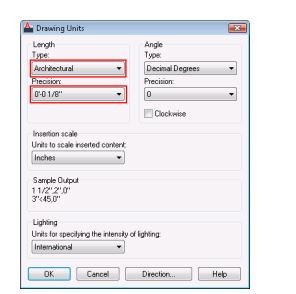
The Sample Output section shows the display style of the drawing units on-screen. Select different length types, such as Decimal, Scientific, Fractional, or Engineering and notice how the sample output changes. For a change in the Length, you can select a desired precision and unit type.
3. For a change in the Angle, you can select the desired precision and angle type.
4. For a change in the Base Angle, you can enter a value for the default 0 angle direction. 0 degrees (East) and a counter-clockwise direction is a default measurement.
The following directions will match the values.
| Value | Direction |
| 0 | East |
| 90 | North |
| 180 | West |
| 270 | South |
6. To change the Lighting Units, you can select a lighting unit type.
7. Finally, click ok, and the customized things will apply on.
Recommended Articles
This has been a guide to how to change units in Autocad. Here we have discuss how to change units in Autocad, Angle Display Precision, Angular Measurement in Autocad, etc. You may also look at the following articles:
- AutoCAD Stretch
- Layer Command in AutoCAD
- Block in AutoCAD
- Text Command in AutoCAD
Source: https://www.educba.com/units-in-autocad/
0 Response to "Autocad Lt Changing a Metric Drawing to Standard Dimentions"
Post a Comment